Then design the Lag compensator to meet the SSE specifications. Design a Lead-Lag compensator for the system.

Lead Compensation Design Problem Given The System Of Figure 11 2 Design A Lead Compensator To Yield A 20 Overshoot And Kn 40 With A Peak Time Of 0 1 Second Holooly Com
Numz denz c2dm numerator denominator.
. We compute the new crossover frequency. Solution for The open loop transfer function of a unity feedback system is given by. R e w a r d s.
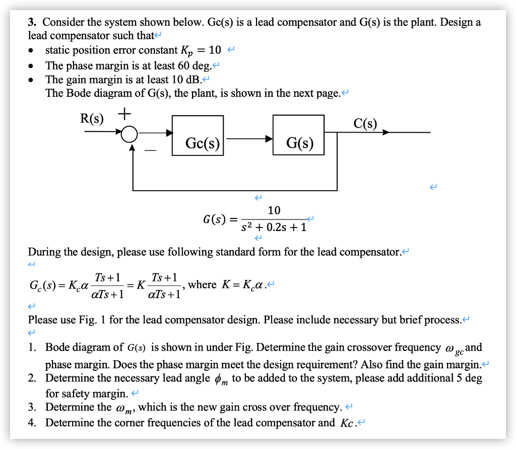
Gs s025s 1 Design a lead compensator to meet the following. 𝐺𝑐 𝐾𝑐𝛼 𝑇 1 𝛼𝑇 1 𝐾𝑐. D Design a lead compensator to meet the following specs.
And the maximum phase shift of the compensator will be ϕ 𝑎𝑥 1 1𝛽 1𝛽 Example 51 For a unity feedback system with a forward transfer function 𝐺 𝐾 50 120 Design a lead compensator for the system in example one to meet the following specifications. Desired system is K. For the transfer function G s I tried to design a lead compensator for the function to have a response to the step with the following specifications.
Z 3 2937 z 2 2875 z 09381. C Design a lead compensator for a unity feedback system with an open loop transfer function Gs to meet the following specifications 18 marks ss4s7 Percentage peak overshoot of 1263 Natural frequency of oscillation. T s 5 s e c 2 C r i t e r i o n.
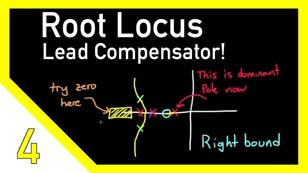
The general design process for designing a lead compensator is as follows. I ts 04 sec. Design a Lead compensator to place the dominant poles at the desired places while neglecting the effects of the Lag compensator.
OS 20 Ts02 K v 50. Gs Plant Transfer function Lead compensation techniques based on the frequency response approach Lead compensator transfer function. The phase-lead compensator design aims at finding the parameter β the time constant τ and the derivative gain K D.
Rs Gcs Gs Solution. VALLIAMMAI ENGINEERING COLLEGE Dept. This compensator simply has 2 poles in the same location and 2 zeros in the same location.
We place the zero for the Lead network one decade under this cros View the full answer. The phase margin is no less than 50circ. 5 - steady state error to a unity rate ramp is equal or less than 005 and - the damping ratio is equal or greater than 07.
Adding a phase-lead compensator to an existing open-loop transfer function can increase the phase margin the bandwidth andor the gain margin. From the settling time spec we see that the real part of. When the main task is increasing the phase margin to a target value the following steps need to be followed.
Ηere is an open-loop transfer function and specifications for compensator design. From the performance specifications determine the desired location for the dominant closed-loop poles. G z 1697 z 2 6679 z 1643 10 5.
Z 3 2937 z 2 2875 z 09381. I defined the required poles and defined the angles according to the normal procedure of the root locus method and determined the zero and pole of the lead compensator. S Compensator Controller.
Consider the sy stem shown bellow it is desired to design a PID controller G. Sketch the root locus of the lead compensated system. We can interconnect this compensator C s with a plant P s using the following code.
System With Compensator and Rate Feedback tabulation is given below. The shape of the compensator is 2We compute the gain K to meet the design requirements this is not the final gain of the compensator. The gain crossover frequency is at least 12 rads.
By cut and try method we choose the following transfer function s3 1 4400 K d for the lag compensator 610. Ii Mp 2. The steady-state error due to a unit-step disturbance input Ds is less that or equal to 5.
In MATLAB a phase-lead compensator in root locus form is implemented using the following commands where Kc z and p are defined. Required for Root Locus The closed loop TF. Analyze the given system via root locus.
Of EIE VALLIAMMAI ENGINEERING COLLEGE SRM NAGAR KATTANKULATHUR-603 203 DEPARTMENT OF ELECTRONICS AND INSTRUMENTATION ENGINEERING CL7101 Control System Design QUESTION BANK UNIT I BASICS AND ROOT-LOCUS DESIGN Part A- Two marks Questions 1. Generally speaking a lead compensator will contribute about 70 degrees to the phase margin 2. G c s s 00345 s 1923 4 10 7 s 2 s 05 and K 122874 but as the question says settling time.
C s such that the closed loop system step response will have 16 overshoot and 1 settling time is 5seconds. For the system above design phase lead compensators to meet the. Lead Compensator Example Design a lead compensator using Bode Plot Method such that Gs Rs Cs 1The velocity error constant Kv 20 sec1 2Phase Margin CsPM 50o 3Gain Margin GM 10.
What is your angle of deficiency. S2 4 400 1 20 s s1 400 K d -96 x Gc s 3 1 500 s s0 400 x from which we find that the system is stable for K d 024. 𝐺𝑠50s2 15s 100.
For the system above design phase lead compensators to meet the following specifications. O S 10 O v e r s h o o t. If more phase is required a double lead compensator can be used 2.
The steps for designing a lead compensator using root-locus. To meet the following specifications Steady state error to a step input is 0 Steady state error to a ramp. Design a lag or lead compensator Cs such that the following specifications are met.
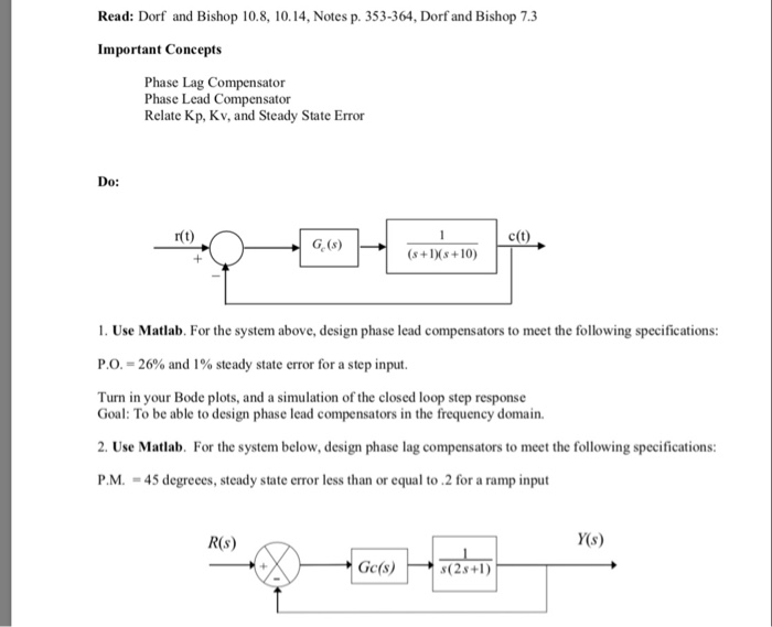
Solved Read Dorf And Bishop 10 8 10 14 Notes P 353 364 Chegg Com
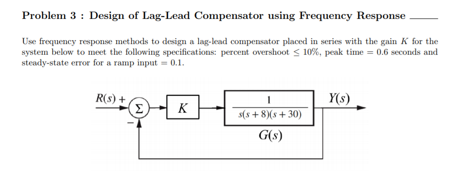
Solved Problem 3 Design Of Lag Lead Compensator Using Chegg Com

Solved C T R T 1 Go S S 1 S 10 1 For The System Above Chegg Com
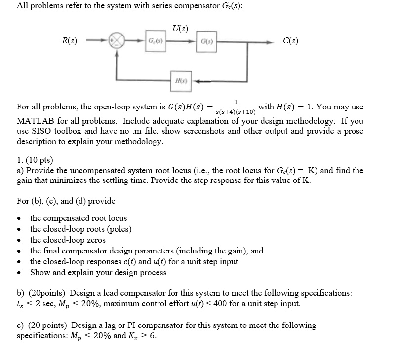
Solved All Problems Refer To The System With Series Compensator Gc S Uls R S For All Problems The Open Loop System Is G S H S With H S 1 You May Use 5 5 4 5 10 Matlab For All Problems
Solved 3 Consider The System Shown Below Gc S Is A Lead Chegg Com
Designing A Lead Compensator With Root Locus Youtube
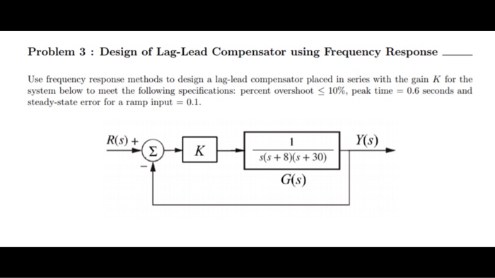
Solved Problem 3 Design Of Lag Lead Compensator Using Chegg Com
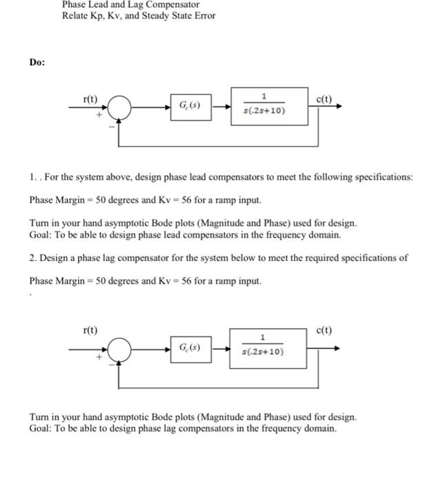
Solved Phase Lead And Lag Compensator Relate Kp Kv And Chegg Com
0 komentar
Posting Komentar